KrosFlo® TFDF® Systems
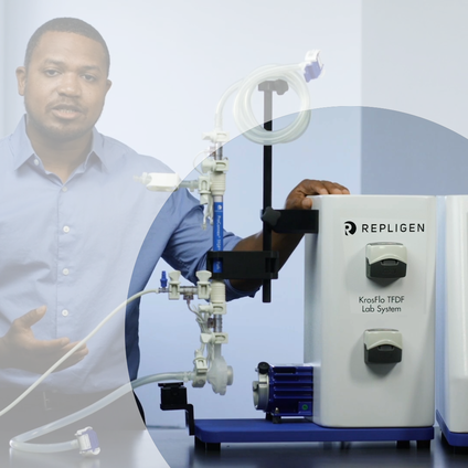
Game-changing TFDF® (Tangential Flow Depth Filtration) technology that simplify and intensify upstream viral vector bioprocessing, ideal for AAV, lentivirus, oncolytic, retrovirus, adenovirus, exosomes, and cells on microcarriers.
INNOVATION BREAKTHROUGH
Unlocking High-Yield Virus Production in AAV and Lentivirus
Intensification Starts Here!
Discover how KrosFlo® TFDF® based process intensification delivers breakthrough in high virus production for transient and stable producer cell lines combined with simplified clarification compared to batch cell culture.
- Implement TFDF to mitigate cell density effect
- Boost virus production >10X and reduce production scale ~20x compared to a 200L batch process
- Simplify clarification techniques to streamline your production process

INNOVATION BREAKTHROUGH
TF + DF = TFDF® Combined Benefits
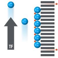
Tangential Flow
High cell density
Poor product passage
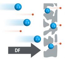
Depth Filtration
Low cell density
Excellent product passage
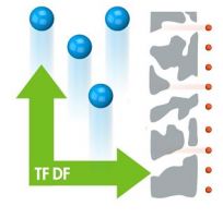
Tangential Flow Depth Filtration
High cell density
Excellent product passage
 INNOVATION BREAKTHROUGH
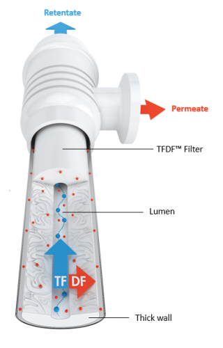
Novel TFDF® Filter
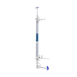
The thick-walled 2 - 5 µM tubular filter captures cells and cell debris with reduced fouling and negligible product retention. The feed stream enters the bottom port. The retentate travels through the lumen and exits at the top of the tube. The permeate exits the enclosure through the lower permeate port.solution. The combination of tangential flow and depth filtration in one filter produces a high-flux, high-capacity solution. h
INNOVATION BREAKTHROUGH
Synergistic Benefits
- Low concentration polarization minimizes fouling
- Short, highly inter-connected paths do not retain product
- Small footprint
- 2-5 micron pore size for large biomolecules

INTEGRATED
Filter, Flow Path and System as One Solution
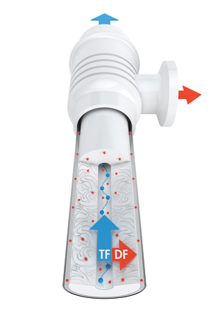
KrosFlo® TFDF® Filter
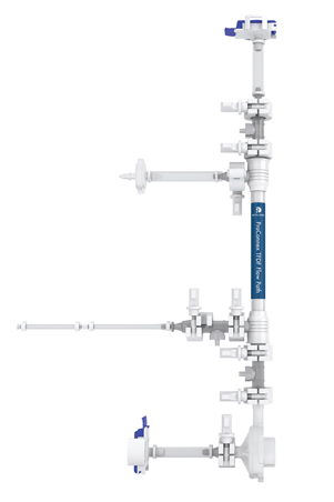
ProConnex® TFDF® Filter Assembly
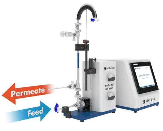
KrosFlo® TFDF® Systems
 INTEGRATED
Complete, Ready-to-use TFDF® Filter Assemblies
Single-use, Gamma-irradiated and closed ProConnex® TFDF® Flow Paths arrive dry, free of sodium hydroxide, glycerin, preservative and ethanol, for a zero flush start state. ProConnex® TFDF® Flow Paths are complete assemblies that include the TFDF® Filter, a disposable pump head, integrated sensors, tubing and aseptic connectors.
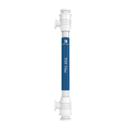
TFDF® Filter
Surface Area: 3 cm2
Surface Area: 30 cm2
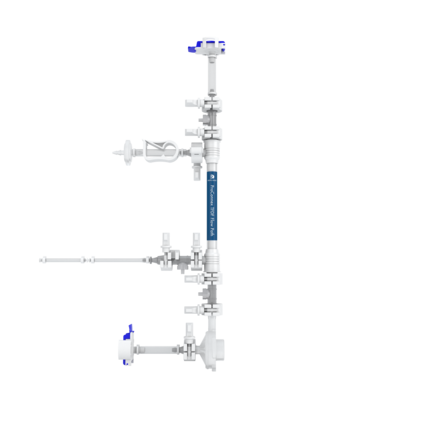
ProConnex® TFDF®
Flow Path
Surface Area: 3 cm2
Surface Area: 30 cm2
Surface Area: 50 cm2
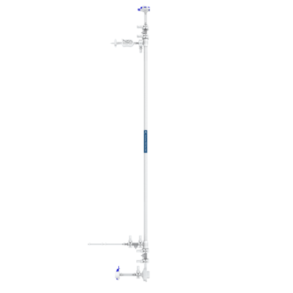
ProConnex® TFDF®
Flow Path
Surface Area: 150 cm2
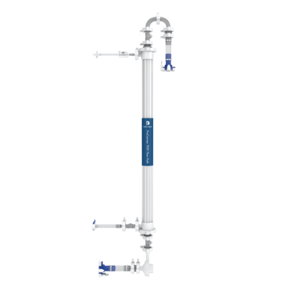
ProConnex® TFDF®
Flow Path
Surface Area: 450 cm2
Surface Area: 750 cm2
Surface Area: 1500 cm2
Surface Area: 2100 cm2
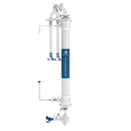
ProConnex® TFDF®
Flow Path
Surface Area: 6000 cm2
Industrial grade components and extended automation allow for confident process scaling. With the same software, hardware, controls and cGMP compliance built into every system, process change challenges in scale-up are removed.
 READY TO SCALE FAST
Maintain processes while scaling to production
The KrosFlo® TFDF® System delivers application-specific process control logic for optimal TFDF process performance. Systems scale from 1 L to 2000 L in a small footprint of 1 m2 for both pilot (31 inch x 42 inch) and process (37 inch x 42 inch) systems.
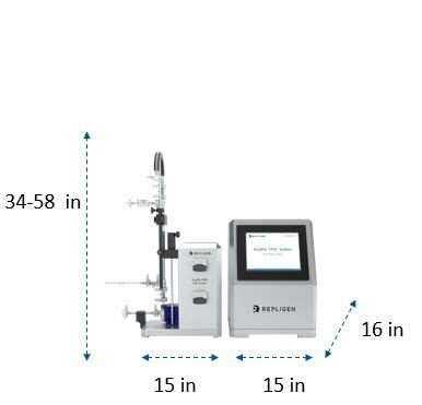
KrosFlo® TFDF Lab System
1 - 50 L volume
3 - 160 cm2 surface area
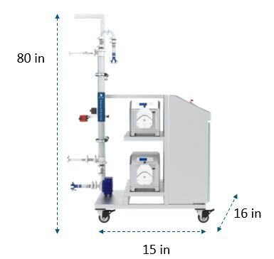
KrosFlo® TFDF® Pilot System
1 - 500 L volume
500 - 1600 cm2 surface area
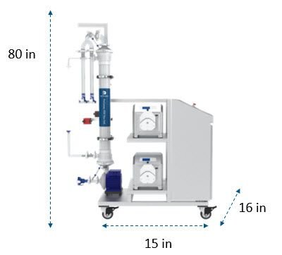
KrosFlo® TFDF® Process System
50 - 2000L volume
3000 - 6000 cm2 surface area
READY TO SCALE FAST
Capacity increases with tube number and length
To ensure linear scalability from 1 to 2000 L, the tube length and the number of tubes per enclosure increases. Tube length increases from 20 cm to 108 cm. The effective length of the filter may be less than the physical length of the filter. The number of tubes increases from 1 - 40 per enclosure.
Number of tubes
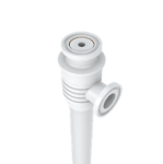
1 tube
Surface area: 3 cm2
Recommended Volume: <1 L
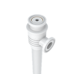
1 tube
Surface area: 150 cm2
Recommended Volume: <50 L
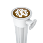
10 tubes
Surface area: 1500 cm2
Recommended Volume: <500 L
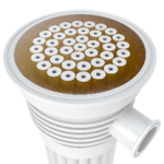
40 tubes
Surface area: 6000 cm2
Recommended Volume: <2000 L
* additional sizes available
Length of tubes
Physical length: 20 cm
Effective length: 2 cm
Surface area: 3 cm2


Physical length: 108 cm
Effective length: 108 cm
Surface area: 150 cm2
KrosFlo® TFDF® Systems
The KrosFlo® TFDF® System delivers a complete solution for optimized tangential flow depth filtration, with integrated process control logic and a single-use, Gamma-irradiated ProConnex® TFDF® Flow Path with integrated sensors.
Click on the tabs to explore features of the different KrosFlo® TFDF® Systems and Flow Paths.
KrosFlo® TFDF® Lab System
1 - 50L volume
3 - 160 cm2 surface area
Click on the links to explore different features.
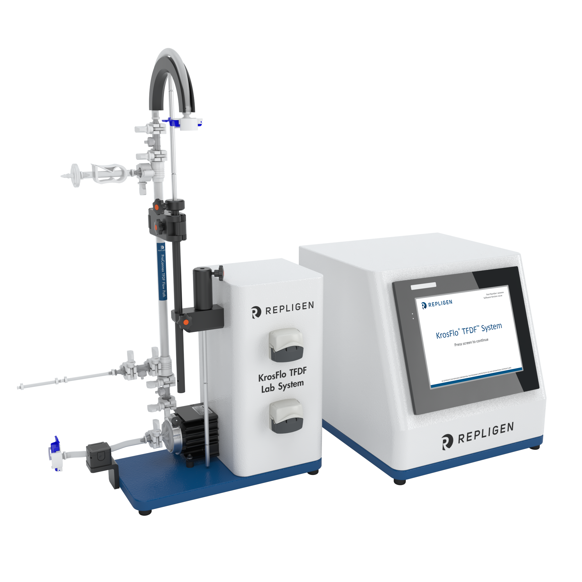
KrosFlo® TFDF® Pilot System
1 - 500L volume
500 - 1600 cm2 surface area
Click on the links to explore different features.
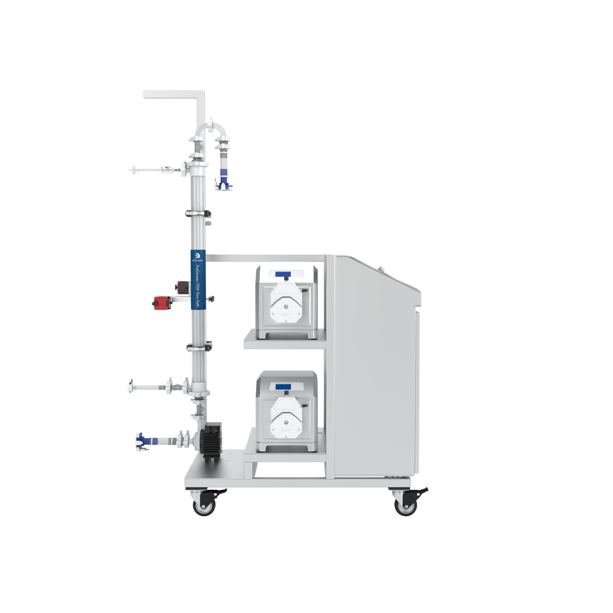
KrosFlo® TFDF® Process System
50 - 2000L volume
3000 - 6000 cm2 surface area
Click on the links to explore different features.
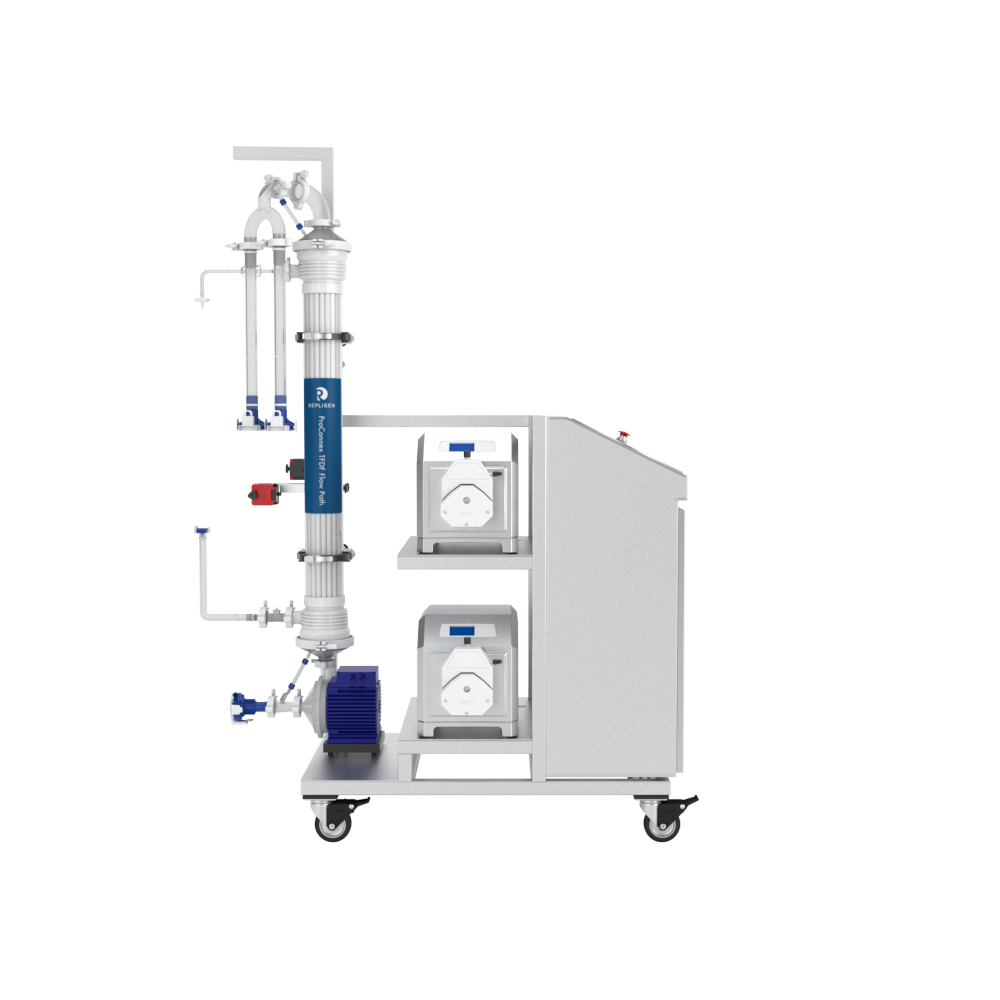
ProConnex® TFDF® Flow Path
Click on the links to explore different features.
KrosFlo TFDF Lab Flow Paths
Off-the shelf, single-use, gamma-irradiated and closed TFDF Lab Flow Paths arrive dry, free of sodium hydroxide, glycerin, preservative and ethanol, for a zero flush start state.

Custom KrosFlo TFDF Pilot and Process Flow Paths
When scaling up, configure a flow path to meet your process requirements for your pilot and process KrosFlo TFDF Systems. All KrosFlo TFDF flow paths are single-use, gamma-irradiated and arrive dry, free of sodium hydroxide, glycerin, preservative and ethanol, for a zero flush start state.

Replace sluggish messy depth filtration with combined tangential flow and depth filtration. No need to load multiple filters or hunt for parts. At 1L through 2000L, connect one fully integrated filter module and go -- at flux speeds up to 1950 LMH.
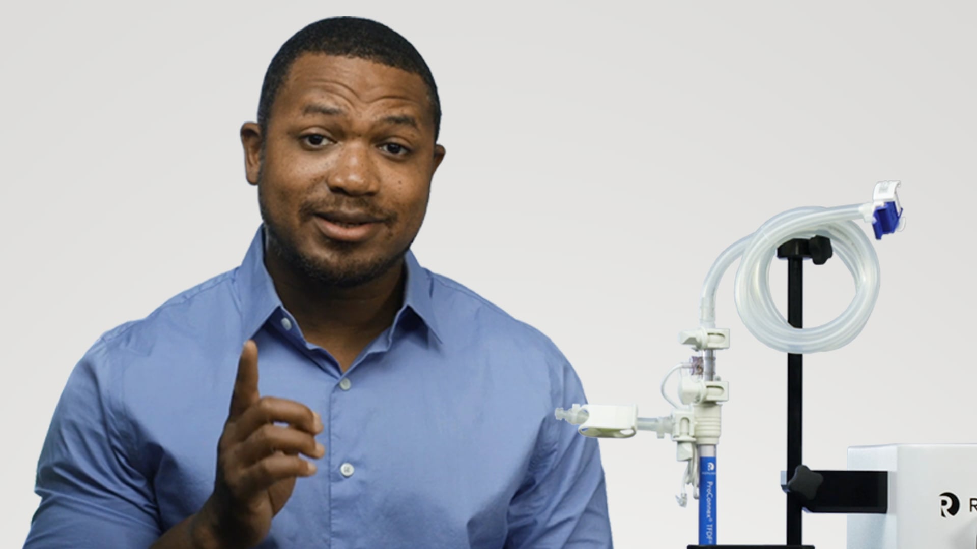
If you have three minutes, then you have enough time to install a TFDF® flow path. Mount the device, make a few connections and you’re done - without ever breaking a sweat.
Manufacturing Centers of Excellence
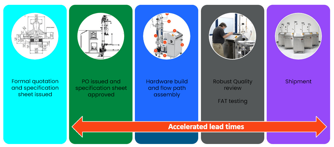
Repligen develops and manufactures products for the biopharmaceutical industry under an ISO 9001 quality management system. We focus on the timely delivery of high quality, consistent and robust products, to ensure business continuity for our customers.
Repligen manufacturing sites are located in Massachusetts, California, and New Jersey in the United States and in Sweden, France, The Netherlands, Germany and Estonia.

Expert Project Management

Customer First.
Support is part of the Repligen DNA. Our goal is to provide exceptional customer experience, and to support the efficient and successful adoption and implementation of all Repligen products and services.
- Field Application Support
- Customer Service
- Field Service Engineers
Resources
Process intensification for lentiviral vector manufacturing using tangential flow depth filtration
by Robert M. Tona, Reeti Shah, Kimberly Middaugh, Justin Steve, João Marques, Blair R. Roszell, Cindy Jung
Cell Press, March 2, 2023
Production of Lentiviral Vectors Using a HEK-293 Producer Cell Line and Advanced Perfusion Processing
by Michelle Yen Tran and Amine A. Kamen
Frontiers, June 14, 2022
Lentiviral vector manufacturing process enchancement utilizing TFDF® technology
by Thomas Williams, Oliver Goodyear, Lee Davies, Carol Knevelman, Michael Bransby, Kyriacos Mitrophanous and James Miskin
Cell and Gene Therapy Insights, April 2020
